Posted on: Dec. 25th, 2020, | By WayKen Rapid Manufacturing
Modern engineering decision-makers consider the use of excessive computational power at this stage useless and as a time-eater. Adoption of techniques involving approximations are much more efficient and help reduce the time required for parametric modeling to execute. Such techniques include Reduced Order Modeling which reduced the mathematical complexity of the system while ensuring that the physics of the governing partial differential equations is kept intact.
After the initial analysis is conducted, an iterative procedure comes into play where the results dictate changes in the design for optimization. This procedure is the linkage between the Conceptual and Preliminary design phases. See more the detail Industrial Design Prototyping.
Let us have a look at a summarized form of the famous Howe model for Project Synthesis Process.
- It is considered as an extension to the feasibility study but with the involvement of greater detail and intricacy.
- The first stage of this process is the selection of one or more configurations.
- The second stage is known as the Flight Regime and Powerplant selection. At this stage, for a given set of operating conditions i.e. Mach number, etc., the powerplant type to be selected is shortlisted i.e. turbo-prop, piston-prop, turbofan, low bypass turbofan, turbojet, ramjet, etc.
- The next stage is regarding the selection of fuselage layout. The details of the payload are often the driving factor behind this stage. This provides a good starting point for the first prediction of aircraft mass.
- Wing configuration comes next. This is a complex procedure for the aerodynamics lab where a large number of parameters are involved. It is a fundamental phase during the preliminary design process. It leads to an initial estimation of lift, drag, the mass of an aircraft and also helps in achieving wing loading estimation calculations after the successive analysis is conducted. Wing loading estimations are conducted based on theoretical equations tuned according to empirical data for various flight conditions. It also helps achieve a rough estimate of the thrust to weight ratio.
- Finally, the parametric analysis stages come into play. The first stage combines wing and fuselage dimensions to produce a set of results for each flight phase. This results in the formation of a design space. Suitable sets of Wing Loading and Thrust to Weight ratios are selected for the second stage of the parametric analysis.
- The second stage of the parametric analysis incorporates the chosen sets of data to calculate the overall aircraft mass. The set which provides the optimal mass value is used to create a referee design which is then used for in-depth analysis and evaluation.
- The referee design is evaluated which in turn provides:
- Estimated sizes for control surfaces
- Aid in completing the landing gear layout
- Better estimation of lift, drag, and mass values
- Revised calculations for performance characteristics based on tuned input data and complex estimation methods
- Repetition of procedure occurs till mass convergence criteria are met
- At the end of this design phase, sensitivity design studies are carried out to identify critical design areas using either graphical or mathematical techniques. Furthermore, other activities are going on simultaneously including the design of hydraulic, electric, fire suppression, ice protection, and pneumatic systems.
The next phase i.e. the Detailed Design phase is where the magic happens i.e. the design is fully defined, scaled models for testing are ordered from a prototype manufacturer and then the final drawings based on Design for Assembly and Design for Manufacturing are laid out with actual topologies, geometries, dimensions, tolerances, and material specifications. Let us discuss this in greater detail now in the next section.
Detailed Design
The focus of this stage is primarily on getting verifications for the design procedures outlined in the earlier phases. It is the most extensive phase of the entire design process. It focuses on each part’s final design, prototyping, and testing. Based on the data acquired from the preliminary design phase, this phase involves the use of Computer-Aided Design and Computer-Aided Manufacturing packages to support design activities.
There are three factors under consideration: performance, manufacturing costs, the time required, and operational efficiencies. For a comprehensive result, there are two types of testing procedures involved i.e. Ground Testing and In-Flight Testing. Let us have a look at the specifics of both types in greater detail.
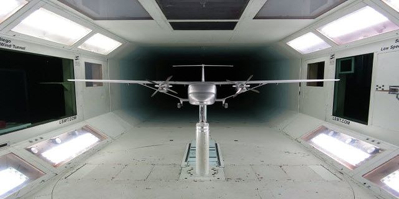
- Ground Testing: It involves wind tunnel tests to validate results from CFD packages, structural tests, avionics evaluation, and systems check. This is the stage where prototyping saves the day. Prototyping scaled parts for initial testing is the key to save costs and precious time. A good prototyping service provider will use appropriate expertise to craft the structure out of the required material specifications from your end. The prototype can be used to analyze strength, stiffness, flutter, elastic stability, and other system parameters. Static loading, dynamic loading, vibrational modal analysis, and flutter analysis are some of the key tests to be performed. For scaled aircraft parts, Stereolithography 3D printing provides the required accuracy for comprehensive evaluation between outlined design and experimental results.
- In-Flight Testing: The involvement of certification agencies to verify the performance and flight characteristics of the actual aircraft. These agencies are known as airworthiness authorities. They evaluate the design of an aircraft based on preset design and safety requirements outlined in Federal Aviation Regulations Airworthiness Standards. The following table comprehensively outlines all airworthiness standards and their respective usage.
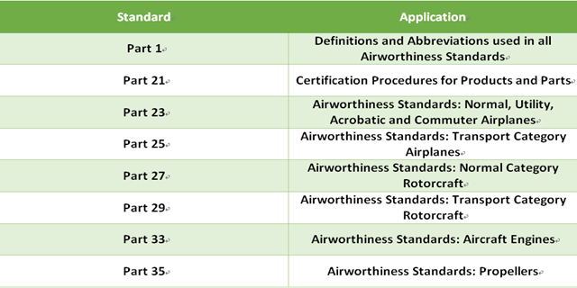
The most noteworthy of these standards include FAR Part 23 which is applicable for normal, utility, and acrobatic aircraft with a Maximum Takeoff Weight (MTOW) of less than 12,500 pounds and 9 or less passenger capacity. It also dictates standards for commuter airplanes having an MTOW of no more than 19,000 pounds with a passenger capacity of 19 or less.
For commercial transport category airplanes like the Airbus A320 or Boeing 737, FAR Part 25 dictates the standards required. Part 25 includes various subparts namely A, B, C, D, E, and F, all dictating standards for the various systems and subsystems of a commercial transport aircraft.
Likewise, for rotorcrafts (most commonly known as helicopters) FAR Part 27 and 29 dictate the standards for normal and transport category respectively. After achieving the airworthiness certifications, the design cycle practically ends with 95 percent of the lifecycle cost incurred by this stage. This is then followed by large scale manufacturing stages.
Concluding the Design Process of an Aircraft
This in-depth review of the design cycle of an aircraft might seem very complex. However, with a step by step approach, mature decisions based on critical thinking, and wise decision making, the design cycle of an aircraft is an achievable feat. In the modern era where stakes are high both in terms of cost and time, the use of prototyping is vital when and where needed because the success of an aircraft design is entirely dependent on comprehensive validation of design ideas. But it is really important to render the services of the right prototype manufacturer in the field of aviation since the accuracy of the prototypes matters a great deal. Any shortcuts taken at any stage of the design cycle prove to be destructive later on like in the case of the Boeing 737 Max recently.